DALY BMS wiring tutorial
更新时间:2020-09-03 10:39:56•点击:57818 • service support
If you need to watch the video, please refer to the bilibili video tutorial https://www.bilibili.com/video/BV1TK4y1e77E/
①Prepare materials, take 13 series and 6 parallel battery packs as an example (4815 battery pack)
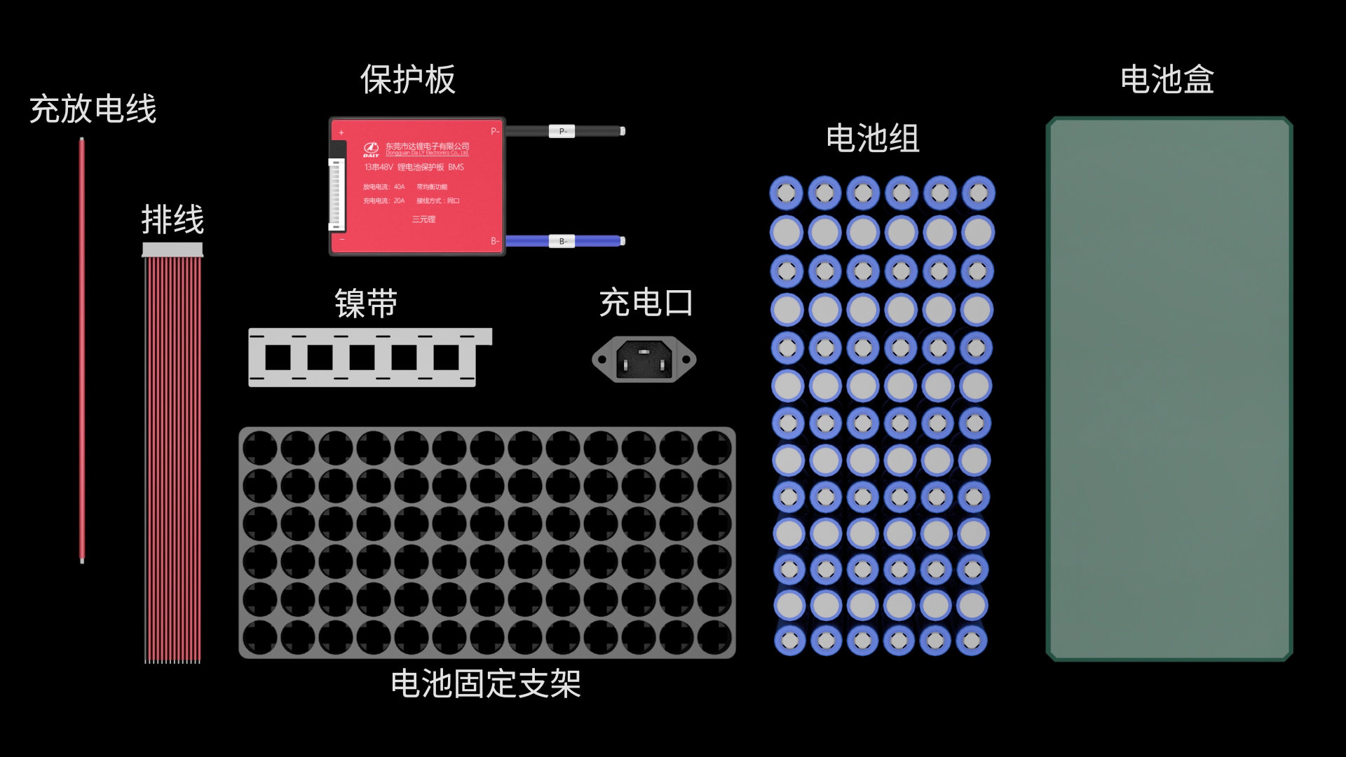
② One 18650 battery cell is 2500mah. To set a 15AH battery, you need 6 in parallel. 15AH/2.5AH=6
③After connecting the batteries in parallel, connect them in series to achieve a voltage of 48V. Series increase voltage
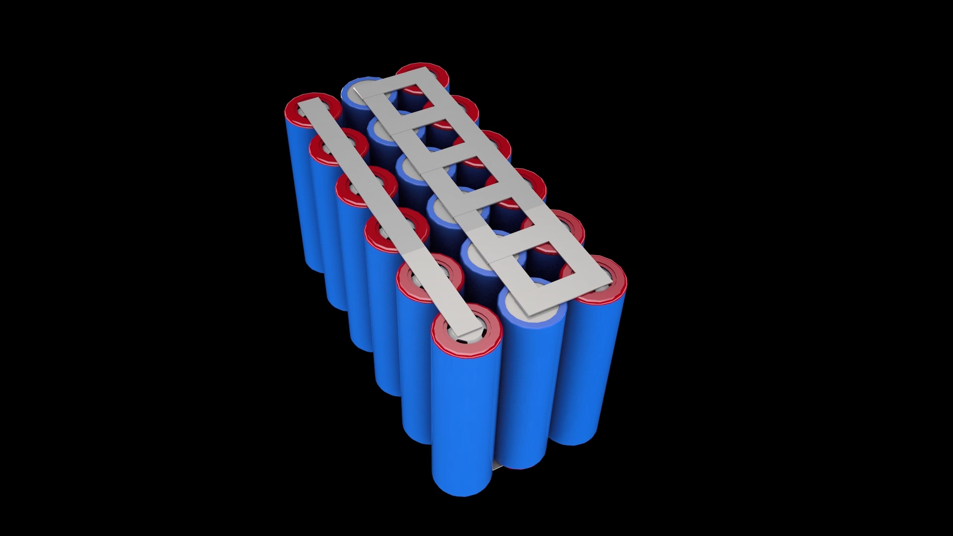
④Fix the battery pack with a bracket. Then spot weld the nickel tape on the battery pack to make the battery pellets form the battery pack.
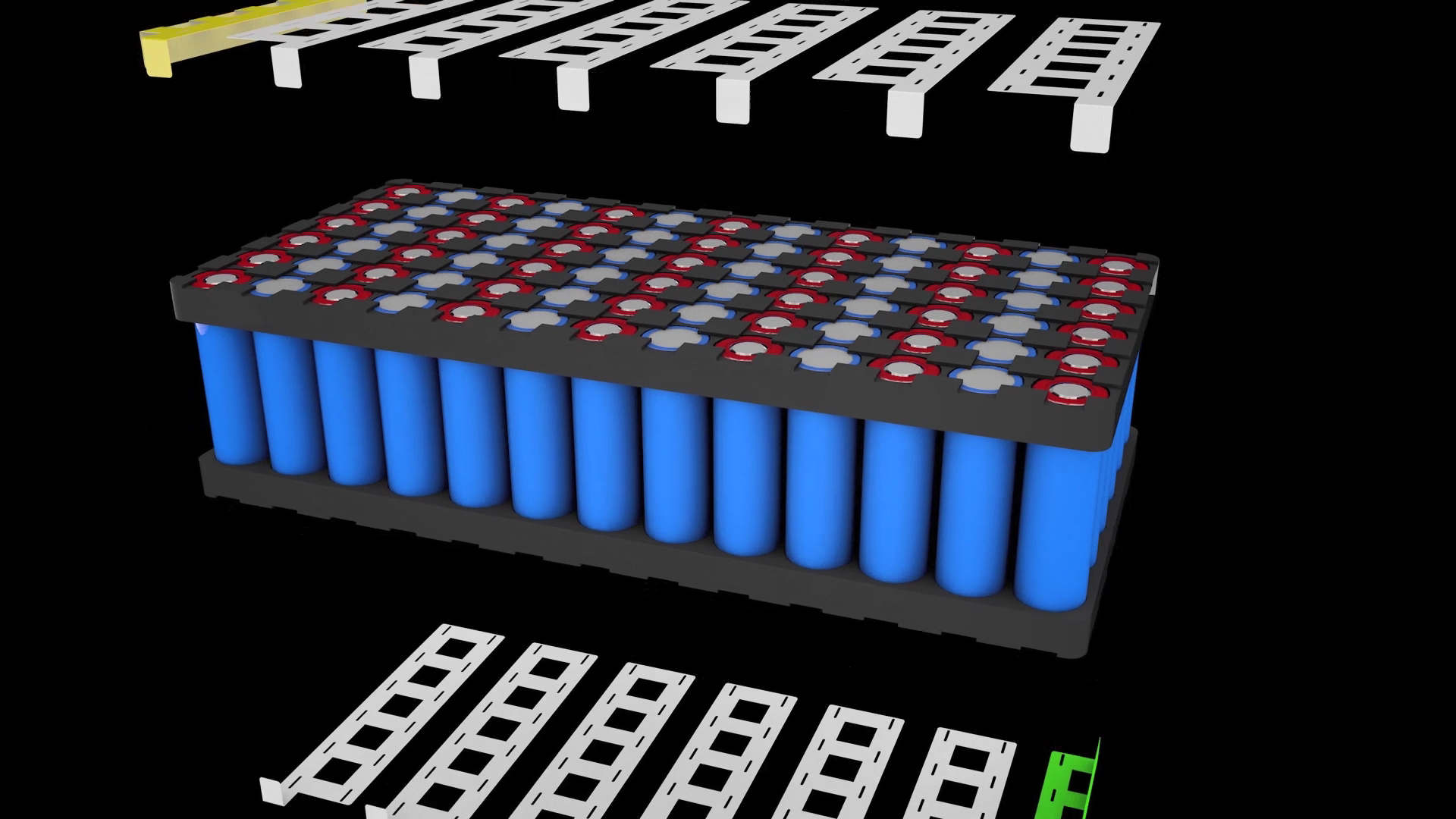
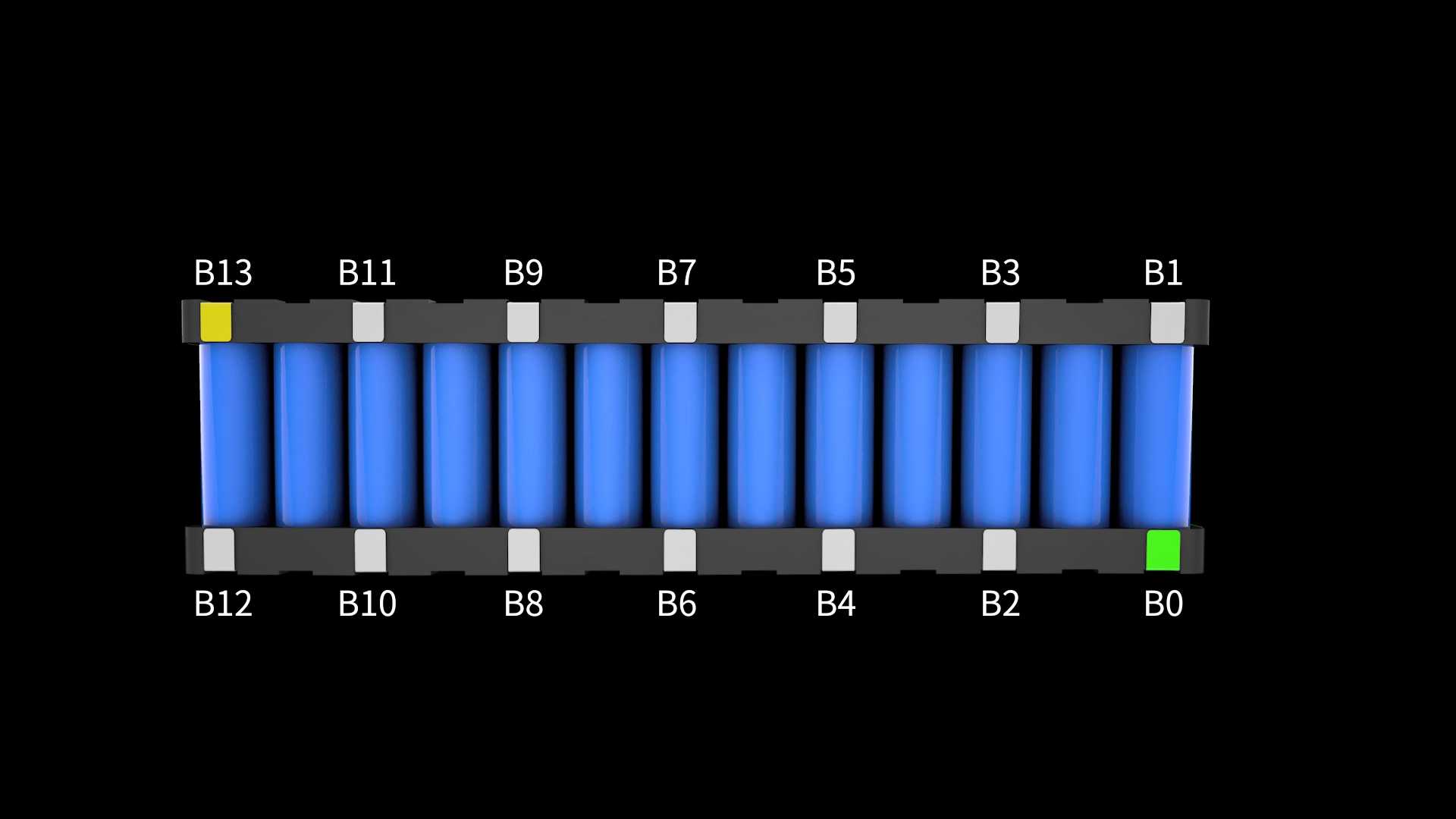
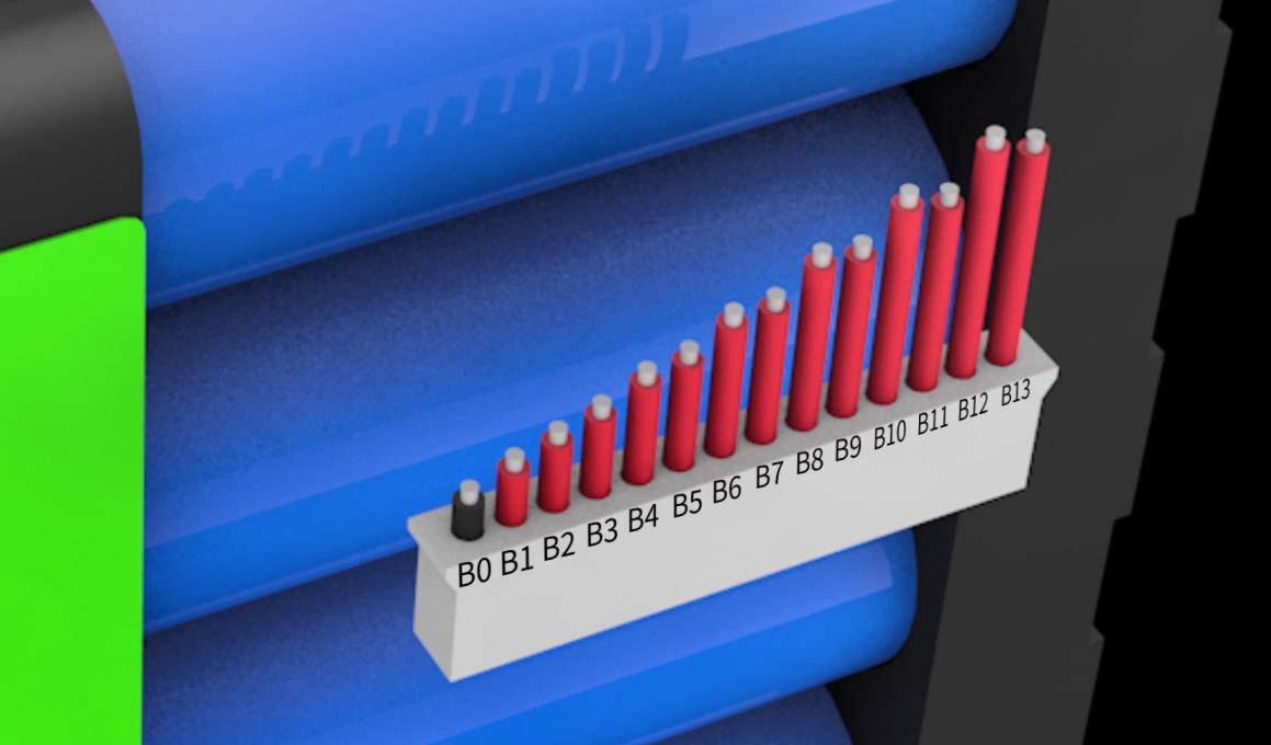
⑤Determine the wiring position of the flat cable. This is a 13-string battery pack and requires a 14-pin flat cable. To ensure the correct wiring sequence, we define the first black line as B0, and then B1 to B13 correspond to B1 to B13 on the battery.
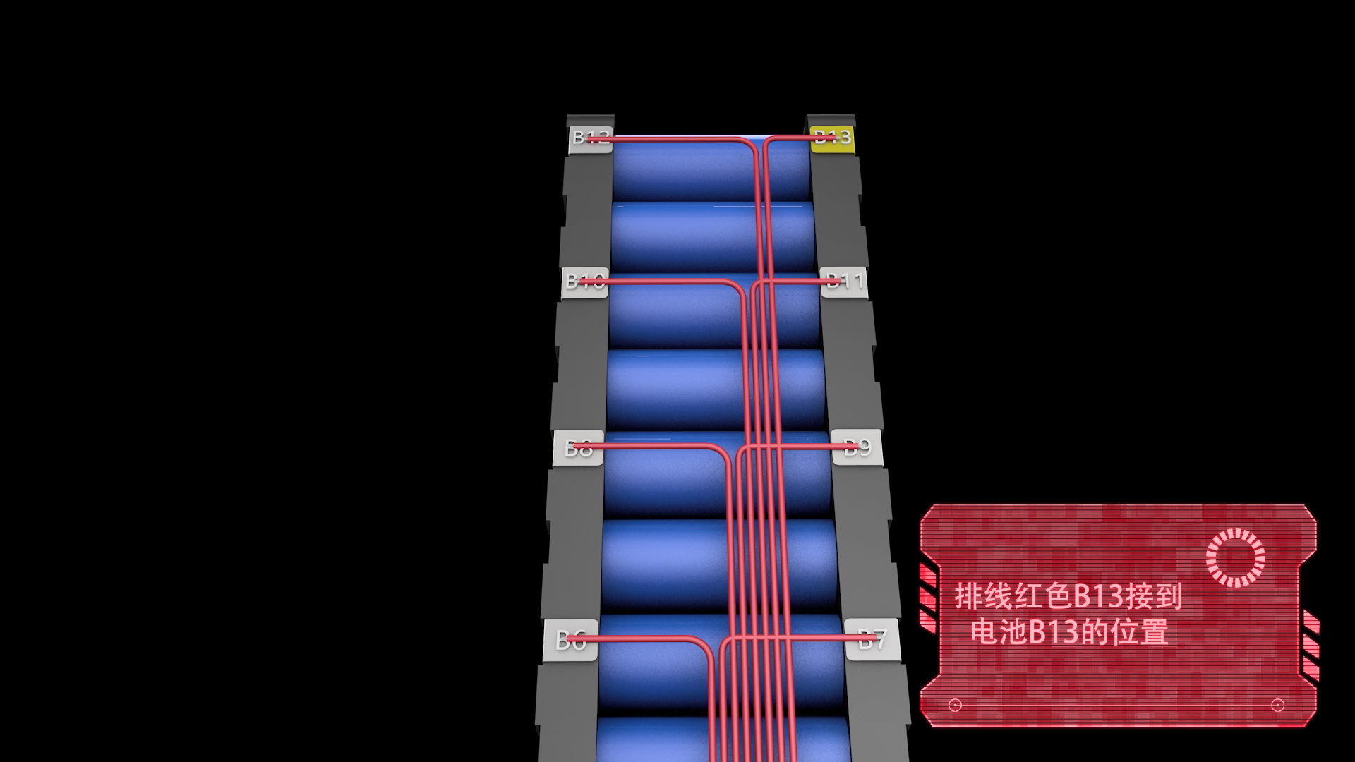
⑥Welding the cable to the corresponding position of the battery pack, pay attention to the protection board when welding the cable
Step by step, connect the B13 cable to B13, which is the total positive stage of the battery
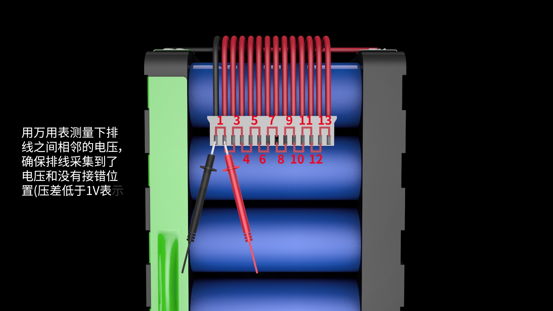
 ⑦Use a multimeter to make sure that the order of the lower cables is not wrongly connected. Plugging in the protection board after the wrong connection will cause damage to the protection board. This step is very important. At the same time, it can also detect whether the cables have collected the voltage of each battery.
A. The voltage between the two cables measured by the multimeter should be consistent with the voltage of the number of strings corresponding to the battery pack, which means that the wiring is correct and you can proceed to the next step, otherwise repeat the previous step for testing.
B. The voltage difference of each string should not exceed 0.5V. If it exceeds 2V, it means there is a problem with the wiring, and the previous step needs to be repeated for testing.
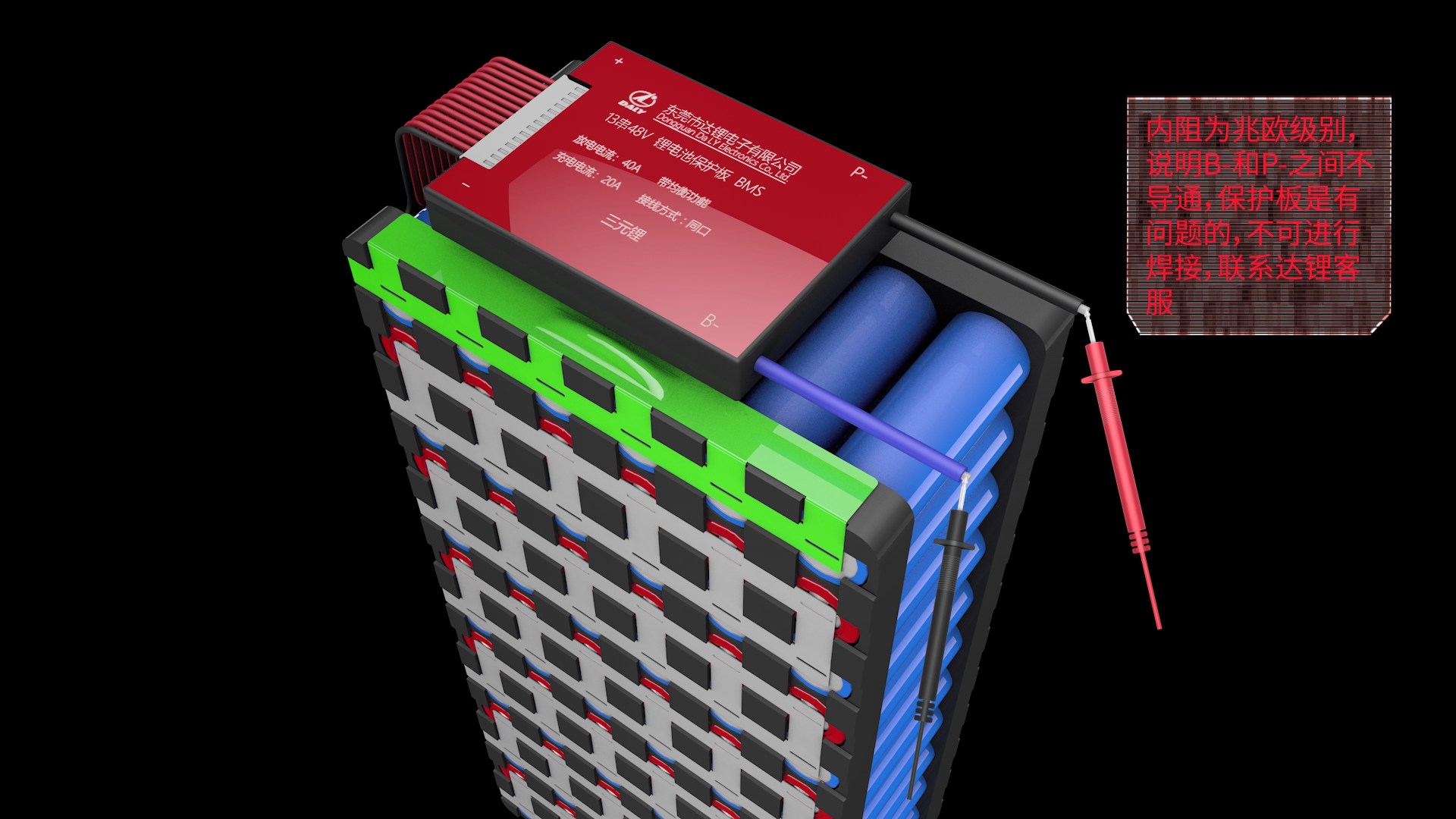
⑧After making sure that the wiring is correct, plug in the protection board and check the quality of the protection board. Set the multimeter to the internal resistance position and measure the internal resistance between B- and P-. If the internal resistance is on, it proves that the protection board is good.
PS: Judging the continuity can be based on the internal resistance value. The internal resistance value is 0 Ω, which means continuity. Due to the error of the multimeter, generally lower than 10 Ω means continuity; you can also adjust the multimeter to the buzzer position when it is on A beep can be heard.
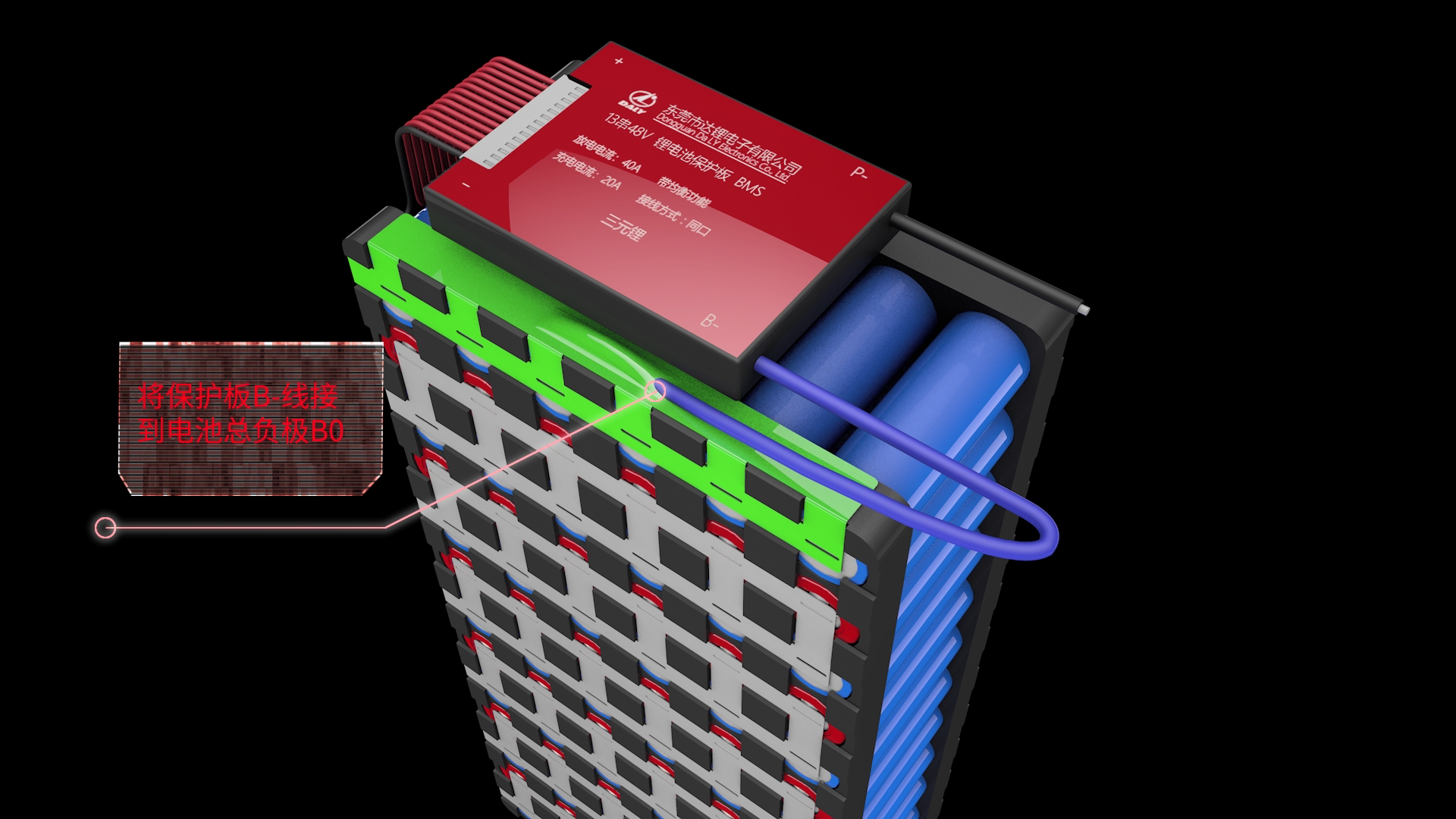
⑨After ensuring that the protection board is good, weld the blue B-line on the protection board to the total negative B- of the battery pack. The P-wire on the protection board is welded to the negative electrode of the charge and discharge.
PS: The charging port and the discharging port of the split-port protection board are separated. You need to connect the extra C-line (usually indicated by yellow) to the negative pole of the charger; connect the P-line to the negative pole of the discharge.
The positive electrode of charging and discharging is directly connected with the total positive stage of the battery pack.
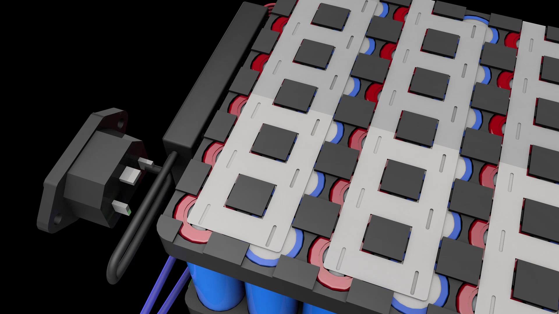
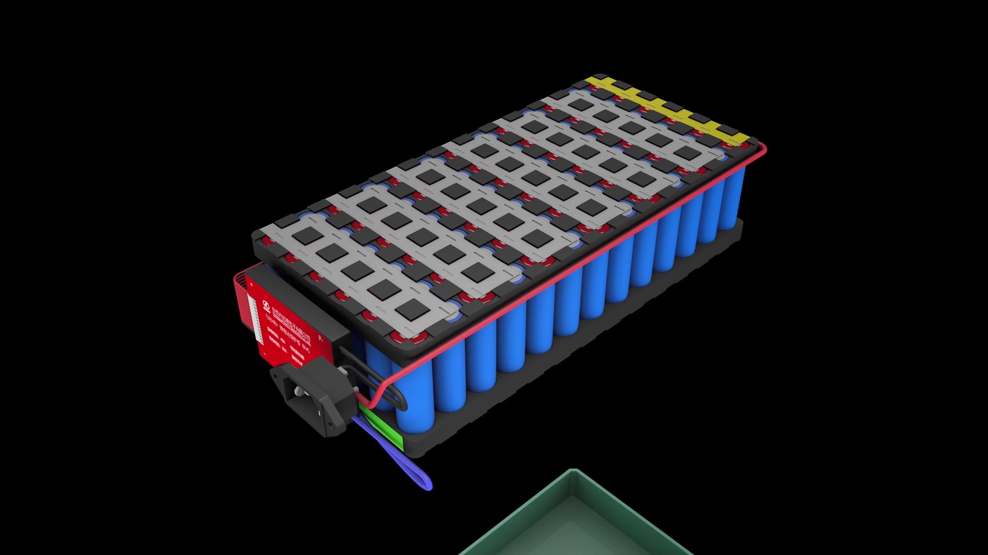
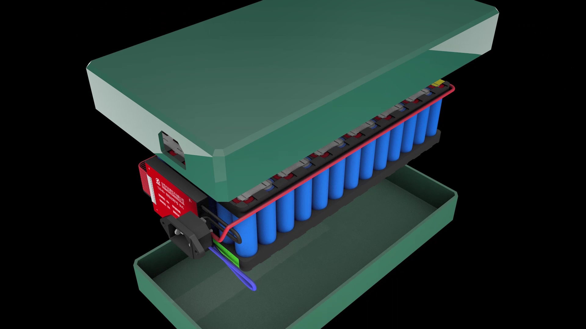
Finally, place the battery pack in the battery box, and a finished battery pack is assembled

Recommended Reading
-
展会
2025-01-20 11:50:50•86410 次
-
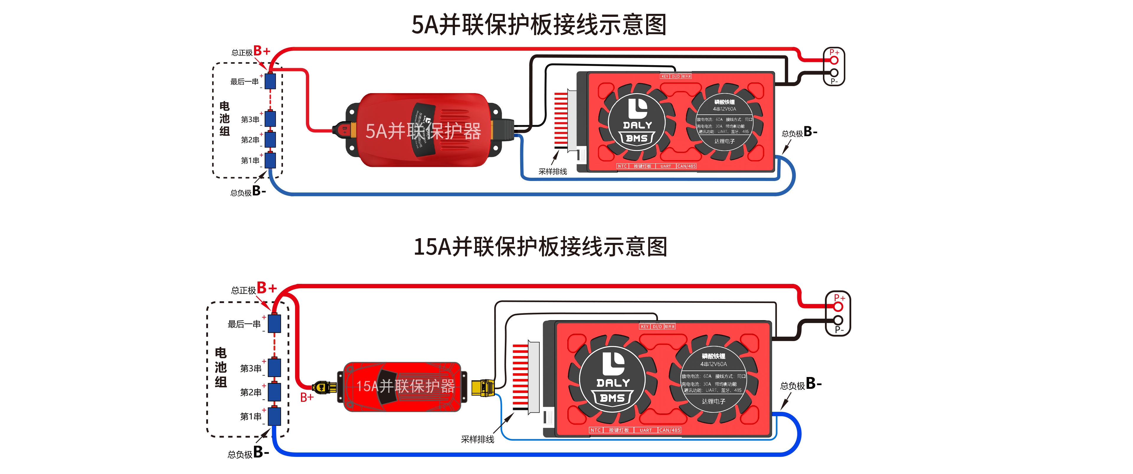
The wiring method of 15A parallel BMS module
2022-01-12 17:02:57•70550 次
-
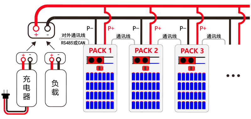
PACK parallel BMS wiring diagram
2022-01-11 11:22:26•353701 次
-

The wiring method of 5A parallel BMS module:
2022-01-11 11:19:01•157166 次


